

This site uses non-intrusive cookies to enable us to provide a better user experience for our visitors. No personal information is collected or stored from these cookies. The Society's policy is fully explained here. By continuing to use this site you are agreeing to the use of cookies.
[as described in the February 1937 edition of the “in-house” LMS Magazine.]
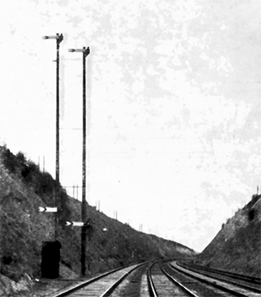
High signals at Tring Cutting
IT is a well known truism that the express train driver runs on the distant signal, and it is therefore a matter of considerable importance to ensure that a driver's view of such signals is the best possible, especially in these days of heavy trains and accelerated services, together with the prospect of even higher speeds in the not far distant future.
For the benefit of those of our readers not in direct contact with operating problems, it may be pointed out that the importance of the distant signal arises from the fact that when "off" it is an indication that the line is clear both at the station or junction immediately ahead, and also right through the next block section up to the home signal of the second signal-box; therefore, a driver, on passing a "clear" distant signal, knows he can continue running at top speed subject to any permanent speed restriction which may have to be observed.
Two factors known as "braking" and "sighting" distance play an important part in fixing the position of the distant signal relative to the first stop signal ahead, which signal is termed the "home" signal.
Braking distance is the space interval required by the heaviest train running at its maximum speed to come to a stand, in which connection allowance has to be made for gradient variations and the adverse effect of a possible greasy rail. In the past a rough and ready computation was to take the braking distance at half a mile, which might be varied slightly according to local circumstances. Whilst this distance sufficed for speeds up to approximately 60 m.p.h., drivers of trains running at higher speeds have to depend on sighting distance, which then becomes of paramount importance, and the necessity for the best possible view of a signal will be realised when it is remembered that a driver running at 90 m.p.h. has only approximately eleven seconds to sight a signal a quarter of a mile ahead, and as his ability to pull up in answer to a "caution" signal varies roughly as the square of the speed at which he is travelling, it will be appreciated that keen sight and alertness on the part of our express train drivers play no small part in the safety of operation.
As an aid in the direction indicated, it has been the practice in the past, on important express routes, to provide very high signals, as shown in the illustration, with top arms often fifty feet above rail level, and lower co-acting arms as a help to sighting when visibility is poor. In clear weather this arrangement leaves little to be desired but, as visibility decreases, the difficulty of sighting the signal increases, until a point is reached where speed has definitely to be reduced.
On the main line out of Euston this difficulty is accentuated by the fact that where four tracks exist there is generally only six feet space between adjacent lines, which does not allow sufficient clearance to permit of a signal being fixed between the tracks adjacent to the road to which it applies, and therefore it has to be fixed outside all lines, as illustrated, the left-hand signal applying to the down fast line, and the right-hand one to the down slow line, i.e., the third line from the left.
An innovation in signalling practice was brought into use on the main line in October last. This consists of mechanically operated colour light distant signals capable of displaying yellow and green lights.
Most readers of the MAGAZINE will be familiar with colour light signals, which although only introduced for main line working in this country about twelve years ago, are multiplying rapidly, but hitherto mainly have been used collectively in complete installations, as at Manchester and St. Enoch, where they are controlled electrically.
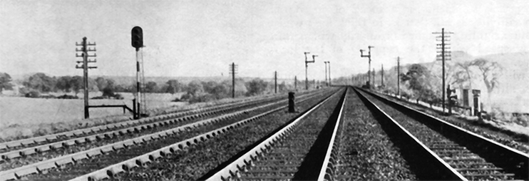
Distant signals at Boxmoor
With the introduction of the grid, power supplies are now becoming available at many points alongside the line, and the opportunity is being taken, as renewals become necessary, to replace the old semaphore distant signals with the latest type colour light signal, which with a consumption of 24 watts, provides an effective beam candle power of approximately 35,000. The light from these signals can be readily seen on straight track at 1,000 yards on a bright sunny day, with the tremendous advantage over the semaphore type of signal that, the worse the background and atmospheric conditions, short of a thick fog, the better the signals show up, and even in a thick fog they are clearly discernible on passing, as they create a coloured aureola on the surrounding haze.
In order to obtain the maximum benefit from the use of these signals, it is essential to fix them so that they are as nearly as possible at a driver's eye level, and as close to him as clearance requirements permit. The very best position is as shown on the left in the above illustration, but as such a signal may not be fixed in so narrow a space as six feet, the distance between the adjacent lines, the only alternatives are to fix it either on a gantry spanning all four lines or, as shown in the lower illustration, as a dwarf signal, this latter alternative only being a practicable one where the approach to it is almost dead straight, as on a curve a train on an adjoining line would hide it from view.
The photographs of the signals illustrated were taken prior to them being brought into use; they are the up slow distant on the left, and the up fast distant as a dwarf between the down slow and up fast tracks, so that each signal is immediately to the left of the driver, whether running on the slow or fast lines.
These signals are the up distant signals for Boxmoor, and replace the two tall signals, which can be seen on the left of the tracks, 387 yards ahead, the distance of the new colour light signals from their respective home signals being 1,400 yards on the fast line, and 1,350 yards on the slow line which, on a falling gradient of 1 in 335, is sufficient for a speed of 70 m.p.h. when visibility is nil, that is, in thick fog; whilst adequate sighting distance ordinarily will permit of any speed within the capacity of the locomotive.
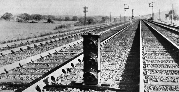
Colour light dwarf signals at Boxmoor
It will be noticed that each signal has three lenses, although only required to display the two aspects, yellow for "caution" and green for "clear". In signal engineering, involving, as it does, safety of operation, little or nothing is left to chance, and, therefore, as a safeguard against a sudden failure of the electric lamp in either of the two main aspects, what is known as an auxiliary yellow light is provided, which automatically comes into action immediately either of the other two lamps burns out, and at the same time the message that this has happened is conveyed to the signalman, a buzzer ringing in his signal-box, drawing his attention to the fact that a light has failed and, by pressing the button at the bottom of the indicator case, he can tell which signal it is, as the small lamp immediately under the labels will fail to light up, and the buzzer can then be silenced by moving the switch below from A to B. The lineman is then sent for, and on a new lamp bulb being inserted in the defective signal and the circuit restored, the buzzer will again sound until the switch is put back to its normal position, i.e., from B to A, so ensuring its readiness for similar duty.
Above the indicator dealing with the individual lamps as just described, will be seen another indicator lettered "power", with the word "off" just below, which is on an internal vane electromagnetically operated to show alternatively "on" or "off". This is another necessary safeguard, because a failure of power from any cause would put all lights out, leaving both signals "dead". To avoid this, secondary batteries are provided, so arranged as to be what is termed "floating" across the mains.
The supply, which is usually about 220 to 240 volts A.C., is first rectified or converted to D.C., current at 12 volts, and it is this rectified current which, in addition to supplying the signals, also keeps the battery charged ready to take up the load should the power fail at any time. This change of supply is automatically brought to the signalman's notice by another buzzer or bell and the indicator just referred to. His instructions are to send for the lineman should the power be "off" for more than fifteen minutes.
Failures of power supply are usually of only short duration, but as a precaution, the battery is of sufficient capacity to light the signals for twenty-four hours.
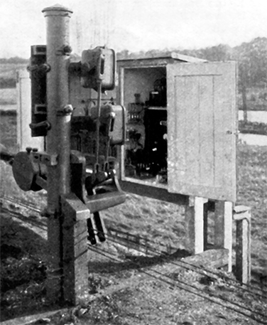
Relay Cupboard and Switch
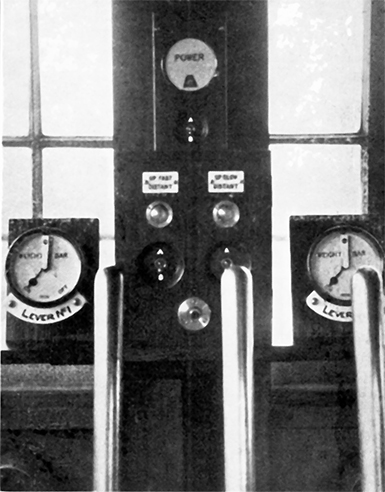
Power-off indicater, light indicator and repeater at Boxmoor
Our last illustration shows the operating arrangements. Mounted on a short tubular post is an ordinary double-side lever plate, to which the wire from the signal-box is attached, but, instead of there being rod attachment to a semaphore arm, it will be seen each is coupled to the arm of a circuit closer. The latter is of a special type designed for this particular purpose, with a snap switch action, and so arranged that full stroke has to be nearly completed before the "off" contact is made, whilst in the opposite direction the lever has to be nearly back to normal before this contact again breaks; there is therefore an ample margin to compensate for expansion or contraction of the signal wire during the period in which a signal-box may be switched out of circuit with all signals off. Embodied in the same circuit closer are contacts actuating the weight bar indicators seen in the earlier illustration. These have a definite relationship to the signal operating contacts, and are set so as not to make the "off" circuit until immediately after the "green" light circuit has been made, and in the return direction not to make the "on" contacts until the snap switch has acted, and the "yellow" light circuit has been made.
It will thus be seen the signalman is kept constantly aware of the condition of affairs at the signals he is controlling, and as far as possible any contingency likely to interfere with the correct presentation of aspect to a driver has been foreseen and provided for.
Up to the time of writing ten examples of such colour light distant signals have been brought into use; at Cheddington, Tring, Northchurch, Berkhamsted and Boxmoor, in connection with the 1936 signal renewal programme, and further similar renewals are contemplated, so that there is every reason to anticipate that in time there will be a chain of such "beacons" stretching right along the main line, aiding our drivers to comply with our Chief Operating Manager's laudable ambition of being always "On Time", quite irrespective of weather conditions.
Site contents Copyright © LMS Society, 2026

February 3rd, 2026
Site contents Copyright © LMS Society, 2026